

Ornament and Crime (v4.1) Build Guide
- filip
- Dec 11, 2025
- 4 min read
10hp Eurorack Multi-Function Module
Difficulty level: Intermediate/Expert
Time: 2-3 hours

This is a Build Guide for the Ornament and Crime 4.1 (aka O.R.N.8.) module. This is a module that runs 4 iterations of Phazerville apps at one time, in addition to a stereo or dual mono DSP processing pipeline.
SOFT WARNING
This module is extremely dense, so the build is quite challenging. Incorrect soldering or damage to components can be devastating, since many components are quite expensive. Take your time, double check component placement before soldering. Many components are not specified by name. Check that the Teensy is installed the right way around. Check that headers are soldered on the correct side. This is a build that you will want to follow this guide for.
SOFT WARNING OVER

CPU BOARD
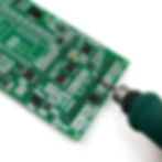
We're going to start with the CPU board - this is the one without jacks, that says "TEENSY 4.1" in the center. We're going to solder the box power header and the H11L1 optocoupler first. Both of these components have polarity, ensure the component matches the footprint. For the optocoupler, the dot on the chip should line up with the notch on the footprint, or just copy the placement in the photo. The optocoupler has a dot on the chip in addition to a round "ON" (ON Semiconductor) logo, don't get confused!


We're going to be flipping back and forth between top side and bottom side to make it easier to fit your soldering iron between components. Next, we're going to solder some headers to connect the two boards together. It's important that these connectors are perfectly straight and sitting flat on the board. If you're not confident in your ability to solder these perfectly, you can use the male pin headers and the other board as a "holder" while you solder.
We'll do the 2x7 pin sockets on the BACK side - not the component side.


Next we can solder the 1x16 pin sockets on the same side as the 2x7s.


Next up are the headers for the Teensy 4.1. These go on the component side. The 5 pins on the inside of the Teensy footprint are not connected and can be ignored.

The 4 pin header can be soldered to the "MIDI IN OUT" location. This is useful if you plan on building or using an expansion. The 2x2 pin header labelled "16 17" is for debugging. This is not needed unless you plan on firmware development.


The Teensy can now be soldered to the 1x40 male pin headers. It helps to use the female pin headers you've already soldered to hold these pins in place.


This completes the CPU board. Set it aside and we'll start on the Jack Board.
JACK BOARD
The 2x7 and 1x16 male pin headers need to be soldered first, once the jacks are placed we won't be able to reach the pins with our soldering iron. Place them on the SMD component side and solder from the jack side. I recommend you use the CPU board to hold and align these pins perfectly for you.


These pin headers are the only components mounted on the back side. We can solder jacks, encoders, and buttons next. The 20 1/8" jacks benefit from "dry-fitting" - place the jacks in the footprints and use the panel to align them while soldering. Don't put too many nuts in place, since you will have to remove them to install the OLED.


Ignore my finger injury in this photo. I'm sorry it's a bit gross.
The more nuts you install the less wiggle room the jacks will have while you're soldering. You can see in the photo below that the jacks are not sitting straight, more nuts or more pressure with a clamp or something is needed.

The buttons do not have a polarity, they can go in 2 of 4 cardinal directions. Make sure these are flush against the PCB - they should "click" in somewhat.

Some M2.5x7mm standoffs need to be installed on the OLED before fitting. Two of these standoffs are screwed directly to the OLED, and 2 are screwed through the panel and into the standoff.


While we're dry-fitting the panel to the board to get the OLED aligned, it is a good idea to fit two encoder nuts on the encoders, so they sit underneath the panel. This is also the time to mount the M3 x 11mm standoffs since it will be difficult to screw these in once the panel is in place.

I like to shimmy one of the encoder nuts up to keep the panel perfectly flat. Once the oled is soldered in you do not want to adjust these - the OLED position will be deciding the "straightness" of this module.
The panel with OLED can be loosely installed and the oled pins can be fed through the footprint pads. Not much header will stick through the back of the module.

Not much header is sticking through here, but the pins are electrically connected. In this photo I was trying to drill out the top oled mounting holes to install some screws from the back, but this is not necessary. The oled has nowhere to go - the header pins are enough.

You're done! Install the CPU board to the Jack Board and fit 2 screws through the standoffs.

Do a power up test - you should see something on the screen immediately instructing you to calibrate your module. If you see this you can install the nuts and knobs.
Congrats!
Calibration
Follow the instructions in the Phazerville Manual to calibrate your module!