

Immutable Clouds Build Guide
- filip
- Apr 26, 2024
- 3 min read
Updated: Apr 29, 2025

THE GRANULAR KING
We are building IMMUTABLE CLOUDS, a DIY Clouds kit. All components are included (like all Immutable kits), all you need is a soldering iron, flux-core solder, side cutters, and some wrenches to attach the hardware.
The kit contains
PCB (SMD Preassembled, and pre-flashed)
Panel
Electronics Parts Bag
Hardware Bag
Power cable
Here is the BOM (a print-out is included in your kit)

Your kit should look like this:


Pull out the Printed Circuit Board (PCB) and empty out the electronics Parts Bag.


We'll start with the 2 tact buttons, these are symmetrical and have no polarity:


Next we'll solder the power header. This is the only component that is placed on the back side, and soldered on the top side. There are two additional footprints on the back, one for a Serial connection, and one for a JTAG port. Neither of these are necessary since your module is preflashed and has a bootloader, so these connectors are not included. For firmware updates you can use the WAV file method.

Next we'll solder the illuminated 'Freeze' button. This is a momentary button with an integrated green LED.
The Illuminated FREEZE button DOES HAVE A POLARITY PLEASE MAKE SURE IT GOES IN THE RIGHT WAY AROUND
There is a green dot which needs to align on the side with a dot on the PCB footprint.

LED TIME
Your kit comes with these really neat LED spacers. They have 3 holes so they accomodate the Bi-Colour LEDs we are using. These LEDs actually have two LEDS packaged into one - one green and one red, with the anodes of each connected to one pin. This allows one LED to glow green or red, or if both are on it will glow yellow.

There is a flat on the LEDs which need to align with the flattened edge on the PCB. Solder these flush, but just solder one pin and check your alignment before soldering the other 2.


Once the LEDs are in a good position, solder the 3 pins for each LED and clip them short with your side cutters.

At this point we will employ a timeless synth-diy life hack and place all the parts, fit the panel over top of them, and then solder them. This ensures the components are located correctly to the panel.
Make note - there is one potentiometer that is different than the others. This one is a dual-gang (2 in 1) A(logarithmic) 50 K Ohm poteniometer. This one fits at the bottom left position. A dual-gang potentiometer is used by Clouds to adjust the gain for both Left and Right input channels in tandem.

With all jacks and pots placed, we can position the panel on top.

Crack open your hardware bag to fish out the nuts required.

Place a few nuts to hold everything together. I went overboard here, just put one or two on.

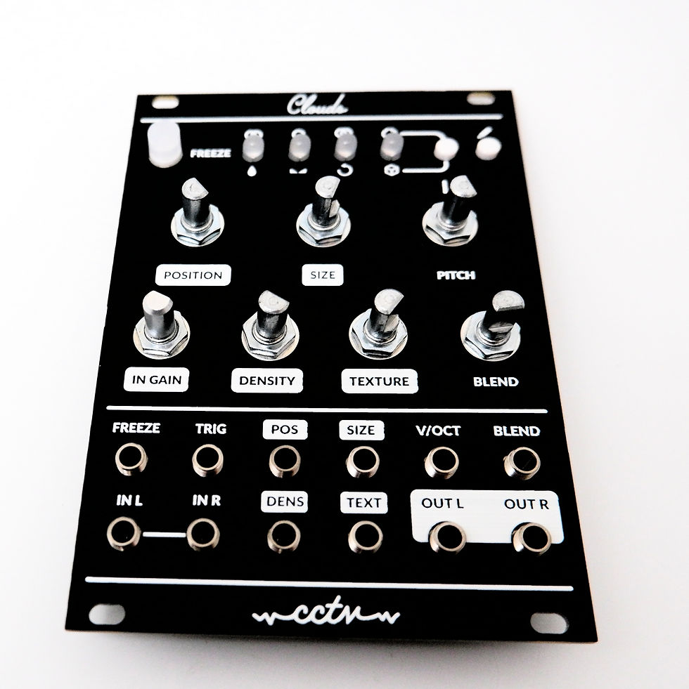


Screw down the remaining nuts and fit your knobs in place. You're done! All that's left is calibration.

To calibrate the unit:
Disconnect all CV inputs.
Connect the note CV output of a well-calibrated keyboard interface or MIDI-CV converter to the V/OCT input.
Press the Load/save button, and while you hold it down, press the Blend parameter/Audio quality button. The first 2 LEDs will blink in orange.
Play a C2 note, or send a 1V voltage from your CV source.
Press the Load/Save button. The four LEDs will blink in orange.
Play a C4 note, or send a 3V voltage from your CV source.
Press the Load/Save push-button.
Calibration is done!
Troubleshooting
The output is very low or non-existent
You may have miscalibrated and sent the same voltage for both steps in the calibration process. For example if you sent 1V(C2) and 1V(C2) instead of 1V(C2) and 3V(C4), the calibration may still pass but you will see some strange behaviour. Check your voltages with a multimeter before calibrating.


Your build guides are the best, Fil! I really appreciate how clear the photos and instructions are 👌